
ENGINEERING GUIDES / 25 OCTOBER 2026
How Does a Thru-Hole (Donut) Load Cell Work?
Full-bridge strain measurement, load-path design and mounting flatness for donut load cells.
Magatom Dynamics force sensing division · Engineering selection note
Axial load becomes a small bridge voltage.
A donut load cell converts elastic deformation into a change in electrical resistance. Bonded strain gauges sense deformation in the annular body. A full Wheatstone bridge combines the resistance changes into a differential signal proportional to excitation and applied force within the calibrated range.
For a sensor rated at 2.0 mV/V and excited at 5 V, the nominal full-scale differential output is 10 mV. At half capacity the ideal net signal is 5 mV, before zero balance, non-linearity, temperature and loading effects. This is a signal example, not a calibration certificate.
The loading annulus must match the drawing.
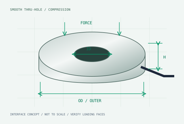
Concept only; the loading surfaces of the supplied model govern assembly.
The shaft passing through the center should stay clear. Force enters a designated loading face and exits through a designated support. On the FUTEK LTH300 example, the inner hub receives load while the outer base hub is supported. A washer spanning both regions can bypass the intended flexure. A cover or cable gland is not a load application surface.
Review parallel structural paths: retaining shoulders, bearings, sleeves or fasteners can carry some force around the sensor. A correct electrical reading cannot recover force that did not pass through the calibrated mechanical path.
Full bridge does not eliminate every off-axis error.
A symmetric strain arrangement can reduce certain bending and thermal effects. The gauge count and layout are design-specific; a full bridge describes the electrical circuit, not a universal requirement for four or eight separate gauge groups. Moment sensitivity and position dependence still need model data or testing.
Check cable pull, nonparallel contact, eccentric loading and support flexibility before attributing unstable readings to the amplifier. Compare repeated loads in the intended assembly, including unloading, to separate repeatability and hysteresis.
Review flatness, hardness and washer geometry together.
Our mounting review starts with a design target of contact hardness at least 40 HRC and flatness better than 0.01 mm. These are project targets rather than universal sensor requirements. A matched pair of hardened parallel load washers can help maintain contact conditions, but cannot correct a wrong support ring or eliminate force shunting.
- Clean and inspect contact surfaces; check burrs and cable clearance.
- Confirm the exact loading and non-loading surfaces from the drawing.
- Provide stiff support and evaluate eccentric force and tightening torque.
- Load and unload in the final assembly and compare with the intended calibration scope.
For a bolt stack with a parallel elastic path, factory sensor calibration may not represent installed sensitivity. Validate the assembled measurement under its actual preload and fixtures.
Read the model-specific installation instructions.
Primary references: FUTEK LTH installation manual, FUTEK LTH300 force-path description, and HBK force-shunt guidance. The illustrative voltage calculation above is derived from rated mV/V × excitation.
Selection route: MT-THL-D smooth donut for compression; MT-THL-B bolt washer for preload. Include the matching hardened washers in your RFQ.