
ENGINEERING GUIDE 04 / 25 OCTOBER 2026
Strain Gauge vs. Piezoelectric Force Washers for Bolt Preload
Define the hold time, force path and torque measurement before choosing a washer sensor or its electronics.
Magatom Dynamics force sensing division · Engineering method and analytical examples
Choose the measurement duration before the sensor technology.
Strain-gauge washers produce a bridge signal with DC sensitivity. That makes them a useful direction for clamping-force holds and preload-relaxation studies. They still have thermal zero/span effects, creep, hysteresis and conditioner drift; a stable long-term reading must be specified and verified under the actual preload and temperature.
Quartz piezoelectric washers suit dynamic forces and can support quasi-static measurements with an appropriate charge amplifier, insulation condition and time constant. Charge leakage and amplifier drift limit longer holds. The useful duration depends on the force level, permitted error and measuring chain; it is not correct to classify every piezoelectric force measurement as incapable of quasi-static operation.
| Measurement decision | Strain-gauge bridge | Piezoelectric washer |
|---|---|---|
| Long preload hold | Specify drift, creep, thermal stability and excitation | Define quasi-static hold duration and charge-amplifier drift |
| Fast force change | Check mechanical resonance and conditioner bandwidth | Often useful for high-dynamic measurement; match amplifier range |
| Signal interface | mV/V bridge conditioner / calibrated digital interface | Charge amplifier matched to sensor sensitivity and cable |
| Installed force shunt | Assess the assembled load path and sensitivity | Preload and shunt sensitivity also require assessment |
Understand what the analytical decay plot does—and does not—show.
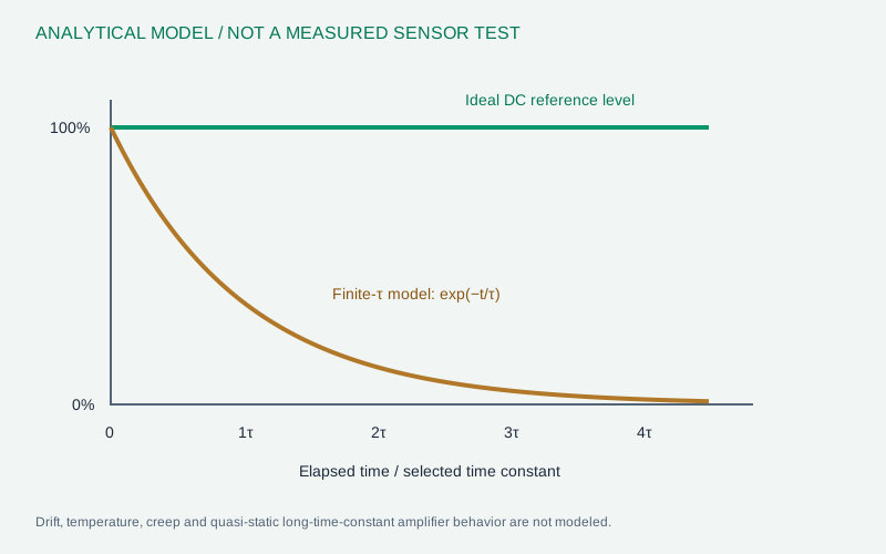
For one idealized finite-time-constant model, Q(t)/Q(0) = exp(−t/τ). At one time constant, 36.8% remains; at three, 5.0% remains. This curve is a circuit model with a deliberately finite τ, not a measured Kistler sensor test. A quasi-static charge amplifier with a long time constant behaves differently, and additional drift must be specified separately.
ISO 16047 measures a tightening characteristic, not a universal preload.
The ISO 16047 scope addresses torque/clamp-force testing under specified conditions. VDI 2230 addresses the calculation of highly stressed bolted joints. Bolt diameter alone cannot determine the required sensor range: property class, friction, bearing area, joint stiffness, tightening method, operating loads and geometry all matter.
A useful first calculation is the torque coefficient K = T/(F × d), where d is the nominal bolt diameter in metres. If torque is 50 N·m, measured clamp force is 25,000 N and d is 0.010 m, K = 0.20. This is an arithmetic example for those stated values. K combines the tested frictional and geometric conditions; it does not separately identify thread and bearing friction without additional measurements.
Calculate K from measured torque and clamp force.
K = T / (F × d), with T in N·m, F in N and d in metres. Use measured assembly values; K includes the effects of the tested thread and bearing friction.
The 1.25× / 1.5× values illustrate headroom selection, not universal ISO/VDI safety factors. Include preload, operating peak, dynamic overshoot, bending and sensor overload limits in the final selection.
Keep tightening torque away from the sensing body.
Use the specified anti-rotation arrangement and loading interfaces. Confirm that the matched hardened washer bears only on the active ring, with clearance above the cover and adequate support stiffness. During tightening, peak loads or torsion can exceed the intended axial measuring condition even if the final preload is acceptable.
A washer adds compliance and stack height. Its stiffness can change the bolted joint and alter the relationship between external load and measured reaction. A full bridge, a raised loading ring or a factory coefficient does not prove that every possible parallel force path has disappeared.
Write the experiment and acceptance criteria into the RFQ.
- Define whether the objective is total clamp force, torque coefficient, individual bolt distribution or relaxation over time.
- Specify preload, peak load, loading direction, hold duration, operating temperature and allowed measurement change.
- Attach the fastener, bearing-surface and sensor-stack drawing; identify any external bypass structure.
- Request the appropriate conditioner, simultaneous torque/force capture, sample rate, filtering and timestamps.
- Agree the installed verification method, reference chain, uncertainty and report format.
For multiple bolts, choose an independent-channel system if the distribution matters. A single analog sum cannot recover the load at each bolt after signals have been combined.
Primary technical references
- Kistler measurement primer: dynamic and quasi-static operation, time constant and drift.
- ISO 16047 scope and VDI 2230 Part 1: test method and bolted-joint calculation.
- HBK force-shunt measurement guidance: installed sensitivity and verification.
- FUTEK LTH400 installation drawing: loading surfaces, cover clearance and installation overload considerations.