MAGATOM DYNAMICS / FORCE SENSING DIVISIONMOQ one / Metric & imperial / Paired sensing systems
ThruHoleLoadCellPRECISION THROUGH THE CENTER

PRODUCTS BY STYLE / MT-AMP-KIT

Pre-Calibrated USB / PLC & Parallel Kits

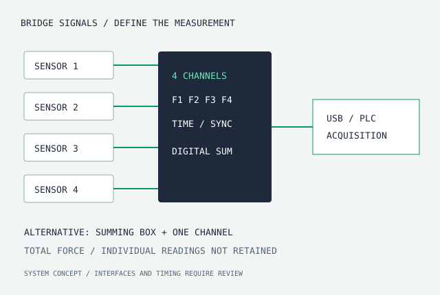
Match bridge excitation, signal range, output interface and calibration to the sensor. Choose a summing box for a calibrated total, or independent channels to retain the force at each mounting point.

Independent sensor channels compared with a summed force signal
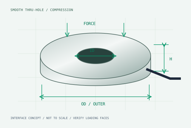
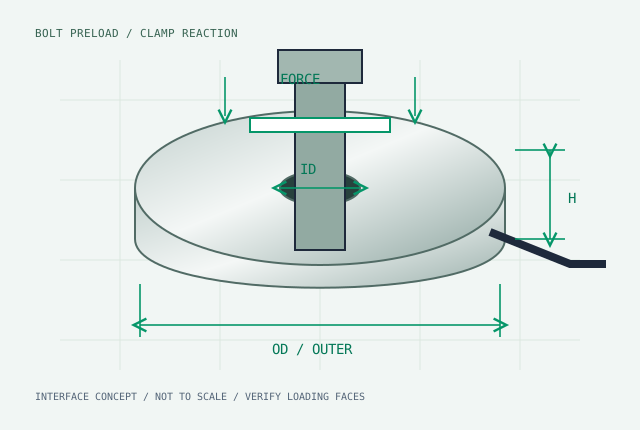
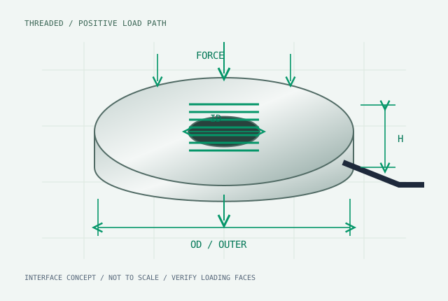
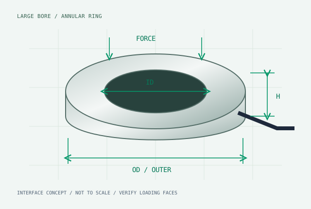
Engineering interface illustration · dimensions from selected drawing
Matched to selected sensorSystem calibration requiredMOQ one
View ID × OD × H matrix ↓

CONFIGURE / EMAIL / REQUEST CAD

Your dimensions. One engineering brief.

Email config & request STEP ↗
Dimension units
Sensor & signal configuration
Mounting, bridge, connector & channels
MT-AMP-KIT-[1CH]-[Single channel]-[USB]-[700ohm]
Email config & request STEP ↗

Dimensions above convert to mm in the reference. $260–$480 indicative bare-sensor range; MOQ one. Confirm the selected drawing, interface, calibration and dispatch in your quote.

Matched analog sum or independent synchronized channels?

Matched analog parallel kit

Two or four bridges with agreed sensitivity and output-resistance matching, trim/position verification and an active total-force output. Request 0–10V, 4–20mA or RS485, plus enclosure and cable scope.

A matching tolerance such as ±0.1% must be defined, tested and included in the accepted system specification.

Independent digital acquisition

Retain each sensor reading before computing the total or force distribution. Request USB, Modbus-RTU/RS485 or EtherCAT; define channel skew, sample rate, filtering, software and timestamps.

Factory sensor/module pairing establishes the agreed electrical scaling. The installed structure still needs loading-path validation.

Plan four independent channels before you sum them.

Enter expected forces at top-left, top-right, bottom-right and bottom-left. Positive x points right and positive y points up from the rectangle center. This is an analytical planning worksheet, not connected instrument data.

Four-corner load planning
Total 4000 N · Shares 25% / 25% / 25% / 25% · Center of force: x 0 mm, y 0 mm

Assumptions: four point reactions at known coplanar corner positions, same axial direction, no unmeasured support. The result does not identify a safe machine load or dynamic synchronization performance.

Specify the matched sensor with the kit.

THROUGH HOLE LOAD CELL SELECTOR

Start with the space you have.

Dimension units
11 candidate option records. Confirm the selected bore/capacity combination and loading faces on the drawing.
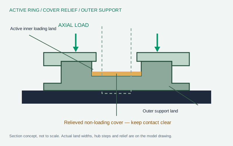
Section concept showing active inner loading ring, relieved non-loading cover and separate outer support ring
Section concept · use the selected drawing for contact dimensions

LOAD INTRODUCTION / KEEP THE COVER CLEAR

Load the active ring. Support the outer ring.

The relieved cover protects the strain-gauge region. A washer must bear on the designated land without touching the cover or connecting the moving load to the fixed support.

Mounting review targets

Contact surface ≥40 HRC; flatness ≤0.01 mm. Matched washer option targets HRC 48 and ≤0.005 mm flatness. Confirm parallelism, loading-land diameters and installed stack height.

Raised hub steps and recess depth are specified on the selected drawing. Factory electrical pairing does not remove the need to assess force shunts, support flexibility or installed preload.

Read the mounting guide →

BRIDGE / DEFLECTION / INTERFACE

Specify the mechanical and electrical handoff together.

ParameterQuotation specificationSelection consequence
Full Wheatstone bridge700 Ω preferred for FUTEK-family review; 350 / 1000 Ω optionsCheck excitation loading, output resistance and self-heating together.
Rated output1.5–2.0 mV/V nominal directionConfirm actual calibrated span, zero and conditioner input range.
ExcitationBy selected MT model and thermal reviewFUTEK LTH300/400 list 18 V maximum; that value is not automatically assigned to every MT model.
Rated-load deflection0.02–0.05 mm design target for specified configurationsRequest a model-specific value; axial stiffness k = F / δ. Thin large-bore designs need their own evaluation.
Natural frequencyRequest the model/fixture data and bandwidthBody frequency, assembled resonance, sampling rate and filter latency are different quantities.
Connector / identificationCable, CC19, M5/M8/M12 or remote sense; optional TEDS33Check contact count, keying, pin assignment, sealing and reader/template compatibility.

Wiring and CAD library → · Paired-system calibration →

PROTOTYPE TO OEM / DIRECT QUOTATION

Price the complete measurement chain.

01 / SENSOR

$260–$480 / pc

Indicative mV/V bare-sensor range. MOQ one for prototype review.

02 / LOAD INTERFACE

+$25 / pair

HRC 48 ground parallel load washers, with loading-land geometry matched to the selected sensor.

03 / CONDITIONING

+$145 standard option

Factory paired USB or standard PLC module. Confirm the exact interface and calibration scope.

Illustrative configuration: $340 sensor + $25 washer pair + $145 standard conditioner = $510/set. Multi-channel, EtherCAT and special environmental options are quoted separately.

Volume quote bands: 1–4 prototypes; 5–19 pieces with a target 15% reduction; 20–49 pieces with a target 25% reduction; 50+ annual OEM agreement. Eligible ID/OD modifications target $0 NRE; new elastic-body designs require a separate review. Final pricing and dispatch appear in the formal quotation.

Review delivery & OEM terms →

Resolve fit, signal and loading before ordering.

Can I use a metric shaft with an imperial bore?

Check the actual clearance, runout and thermal range. Nominal inch conversion alone does not establish an assembly fit.

Are washers and paired conditioning included?

Choose the +$25 washer pair and +$145 standard conditioner options in your brief. The quote confirms the selected load interface, signal and calibration scope.

What establishes replacement compatibility?

The original part number and revision, dimensions, loading faces, bridge resistance, excitation, pinout and calibration must match the accepted replacement specification.

QUOTE / CAD / CALIBRATION SCOPE

Your dimensions go straight to engineering.

Send the selected model, interface and application. Request a 2D tolerance drawing, 3D STEP model and a sensor-only or paired-system quotation.

[email protected]

Initial-response target: 4–12 business hours, normally within one business day. Drawing turnaround and dispatch are confirmed with the configuration.

RFQ input units
Include in quotation
Review the exact engineering brief
Hello ThruHoleLoadCell.com engineering team,

Request: Quote & 3D STEP
Reference: MT-AMP-KIT-[1CH]-[Single channel]-[USB]-[700ohm]
Catalogue/model: Custom configuration
Series: MT-AMP-KIT
Bore / nominal thread diameter: TBC mm
Outer diameter: TBC mm
Height: TBC mm
Force: TBC N
Mounting: Smooth bore
Thread / engagement: Not specified
Bridge: 700 ohm
Signal: USB
Conditioner module: Requested (+$145 standard module; quoted interface scope)
Connector/cable: Integral shielded cable
TEDS Template 33: Not selected
Hardened washer pair: Not selected
Channels: 1
Channel architecture: Single channel
Original model / revision: Not specified

Please confirm the selected dimensional combination, loading faces, pinout, calibration scope, lead time and quotation.

Your brief is used to evaluate and respond to this request. Privacy policy. Request a secure transfer method for confidential CAD.

Use email with the same configuration ↗

Compare adjacent load paths.

Mounting & bridge guide · Parallel acquisition guide