
ENGINEERING GUIDES / 25 OCTOBER 2026
Load Cells in Parallel: Summing Box or Independent USB Channels?
Compare calibrated total force with individual bolt loads, excitation current and synchronization.
Magatom Dynamics force sensing division · Engineering selection note
Two bridges in parallel do not simply double the voltage.
Consider two equal-resistance sensors with identical capacity and sensitivity, supplied with the same excitation. In a simplified Thevenin model, their parallel output is the average of their individual signal voltages. Two 10 mV signals still produce 10 mV, not 20 mV. The measuring system is calibrated so that this full-scale ratio represents the combined rated force.
For identical sensors, Vout ≈ (V1 + V2) / 2. For unequal output resistances, Vout ≈ Σ(Vi / Ri) / Σ(1 / Ri), before conditioner input loading and cable effects. Mismatched sensitivities or resistances therefore change weighting. A summing box can provide trim; it does not make arbitrary sensors interchangeable.
A total-force channel cannot reveal the overloaded corner.
| Decision | Summing box + one channel | Independent acquisition |
|---|---|---|
| Calibrated total | Yes, after system calibration | Software sum after channel calibration |
| Individual bolt / corner force | Not recoverable from one total | Retained per channel |
| Eccentric load detection | Needs additional information | Compare channels and positions |
| Dynamic comparison | One combined waveform | Check shared timing and channel skew |
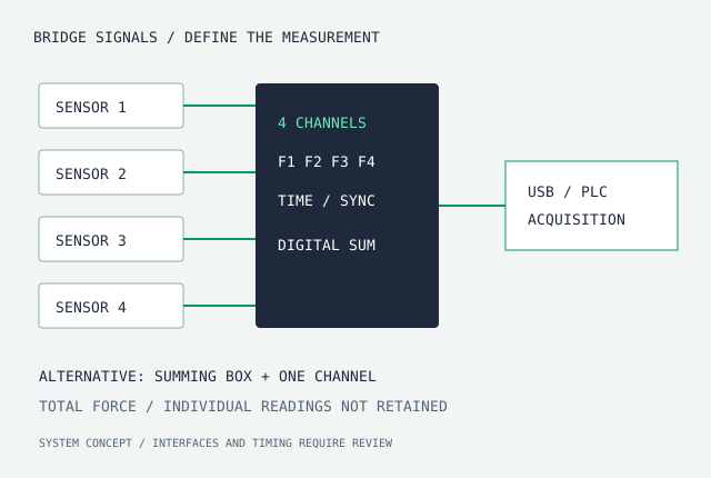
For a four-corner press fixture, equal total force can conceal unequal support loads. If balancing or overload detection matters, retain independent channels and apply a separate limit to each sensor. A software sum should not hide an overloaded channel.
Size the excitation supply for every bridge.
Four nominal 350 Ω bridges in parallel present approximately 87.5 Ω to the excitation source. At 5 V this requires about 57 mA before cable and other losses. Check the amplifier’s permitted bridge impedance and current, voltage at the sensors, and temperature rise. This calculation is an example; actual input and output resistances come from the sensor datasheet.
Wire only compatible passive bridge outputs as the approved conditioner instructions specify. Do not directly parallel USB devices, RS485 transmit outputs or voltage/current amplifier outputs to create a force sum. Digital devices require supported addressing, bus wiring or separate interfaces.
Calibrate the installed system and define synchronization.
Record sensor serial numbers, each channel’s span and zero, loading direction and cable configuration. For a summed system, check different load positions as well as total force. For independent channels, define sample rate, simultaneous versus multiplexed conversion, interchannel skew, filters and latency. A high nominal bit depth alone says little about noise-free resolution or closed-loop response.
Primary installation context: FUTEK LTH electrical and mechanical installation manual. The parallel voltage and current relationships above are circuit-analysis examples with explicit equal-bridge assumptions. Confirm the actual summing-box wiring and amplifier limits before connecting hardware.
Selection route: MT-AMP-KIT conditioning review with bolt force washers or annular sensors. Request a calibrated total-force kit or independent four-channel USB system; specify which readings must remain available.