
PRODUCTS BY STYLE
Match the bore.
Then match the force path.
Compare through hole load cell families by smooth or threaded interface, clamping geometry and central passage. OD and height are confirmed against the proposed drawing.
01 / MT-THL-D↗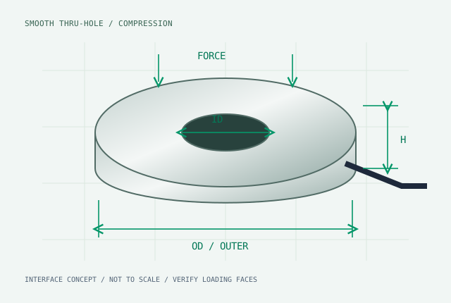
100 N–200 kN02 / MT-THL-B↗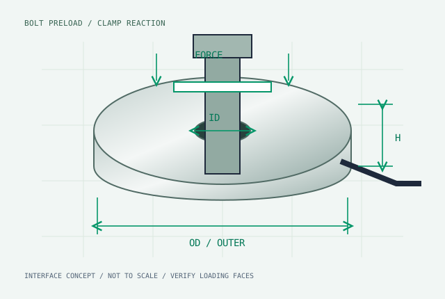
2–500 kN03 / MT-THL-T↗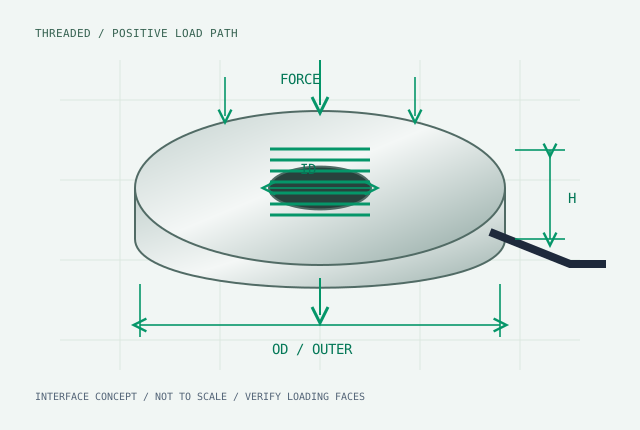
200 N–100 kN04 / MT-THL-LP↗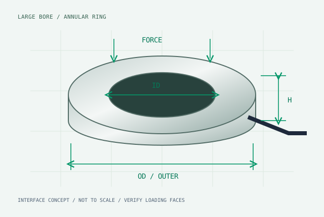
500 N–20 kN light force / to 500 kN heavy05 / MT-AMP-KIT↗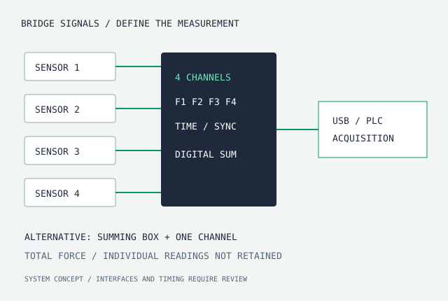
System calibration required
Smooth donut
Ball and roller screw thrust, bearing reaction and fixture clamping
3–50 mm / 1/8–2.0 in100 N–200 kN02 / MT-THL-B↗
Bolt force washer
Bolt preload monitoring, flange clamp force and torque-to-tension studies
M4–M30 / 1/4–1.0 in2–500 kN03 / MT-THL-T↗
Threaded tension / compression
Hollow-shaft tests, center-hole jacks and cable tension fixtures
M6–M36 / TF & TS interfaces200 N–100 kN04 / MT-THL-LP↗
Large-bore annular ring
Robotic hollow joints, hollow-shaft motors and wafer press fixtures
40–120 mm / large-bore options500 N–20 kN light force / to 500 kN heavy05 / MT-AMP-KIT↗
Conditioning & acquisition
PLC press control, paired sensor acquisition and multi-bolt force monitoring
Matched to selected sensorSystem calibration required
MODEL OPTIONS / DIMENSION MATRIX
Choose ID × OD × height.
| Model | ID / nominal thread | OD | Height | Capacity options | Non-linearity / interface | Drawing & quote |
|---|---|---|---|---|---|---|
| MT-THL-D-ID05-OD255.1 mm clearance bore; nominal 3/16 in hardware is 4.7625 mm. | 5.1 | 24.9 | 7.1 | 200 / 500 / 1000 / 2000 / 4500 | ±0.20% FS IP66PTFE cable / M5 option | Get STEP & PDF →Configure → |
| MT-THL-D-ID06-OD25Select 6.2 mm metric or 6.58 mm clearance variant separately. | 6.2 / 6.58 | 24.9 | 7.1 | 200 / 500 / 1000 / 2000 / 4500 | ±0.20% FS IP66PTFE cable / M5 option | Get STEP & PDF →Configure → |
| MT-THL-D-ID08-OD258.2 mm clearance bore; confirm bolt tolerance and runout. | 8.2 | 24.9 | 7.1 | 500 / 1000 / 2000 / 4500 | ±0.20% FS IP66PTFE cable | Get STEP & PDF →Configure → |
| MT-THL-D-ID10-OD2510.2 mm metric and 9.75 mm imperial-clearance variants are distinct. | 10.2 / 9.75 | 24.9 | 7.1 | 500 / 1000 / 2000 / 4500 | ±0.20% FS IP66PTFE cable | Get STEP & PDF →Configure → |
| MT-THL-D-ID12-OD3838.1 mm is our supplied catalogue OD; check original LTH350 revision separately. | 12.2 / 12.9 | 38.1 | 12.7 | 5000 / 10000 / 15000 / 22000 | ±0.15% FS IP67Cable / CC19 option | Get STEP & PDF →Configure → |
| MT-THL-D-ID16-OD5015.2 mm shaft and 16.2 mm bolt-clearance options require a selected drawing. | 16.2 / 15.2 | 50.3 | 16 | 10000 / 25000 / 45000 | ±0.15% FS IP67CC19 option | Get STEP & PDF →Configure → |
| MT-THL-D-ID25-OD76Bore/capacity combinations and loading-land width require confirmation. | 25.4 / 30 / 38.1 / 50.8 | 76.2 | 25.4 | 50000 / 100000 / 220000 | ±0.20% FS IP67Industrial connector / armored cable | Get STEP & PDF →Configure → |
| MT-THL-B-M06–M12Range row: individual bolt size sets OD/H; allow approximately 4 mm extra for the quoted washer pair. | 6.4 / 8.4 / 10.5 / 13 | 18–28 | 6–10 | 15000 / 25000 / 40000 / 60000 / 80000 | ±0.20% FS IP67 / IP68 optionAnti-rotation slot / washer pair | Get STEP & PDF →Configure → |
| MT-THL-B-M16–M24Range row: determine the selected bolt size, loading faces and final stack height. | 17 / 21 / 25 | 36–52 | 12–16 | 100000 / 160000 / 250000 / 350000 | ±0.20% FS IP68 optionSealed cable / ground washer pair | Get STEP & PDF →Configure → |
| MT-THL-TF-M12–M24TF internal threads, M12×1.75 to M24×2; bore value is nominal thread diameter, not a smooth pass-through. TS flange variant is separately specified. | 12 / 16 / 20 / 24 | 41–76 | 15–25 | 2000 / 5000 / 10000 / 20000 / 50000 / 100000 | ±0.10% FS IP674-pin / 6-pin options | Get STEP & PDF →Configure → |
| MT-THL-LP-ID60–ID110Range row: 8/16-gauge layout is design-specific. Heavy-duty variants to 500 kN require a separate drawing. | 60 / 80 / 100 / 110 | 85–145 | 8–12 | 1000 / 5000 / 10000 / 20000 | ±0.15% FS By sealing optionLow-profile side cable | Get STEP & PDF →Configure → |
Center-hole & hollow load cell terminology →
Request a selection review →